[REQ] GoogleEarth Meshes boolean subtract
-
Yes there are sometimes tiny usually vertical gaps because the meshes aren't exactly the same vertically or horizontally in the overlap areas.
-
Looks like I need to extend the faces vertically especially on the low side because, in yout test model, the bounding box of the mesh on the right surfaces momentarily on the mesh to the left which would result in some triangles along that edge not to be "cut" by the intersection.
-
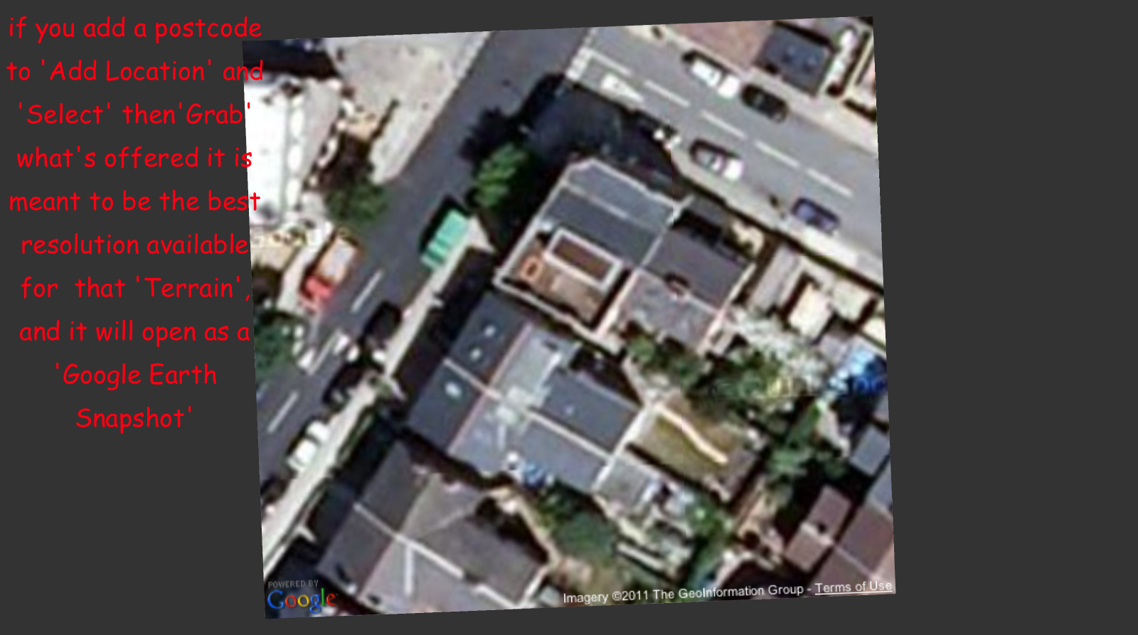
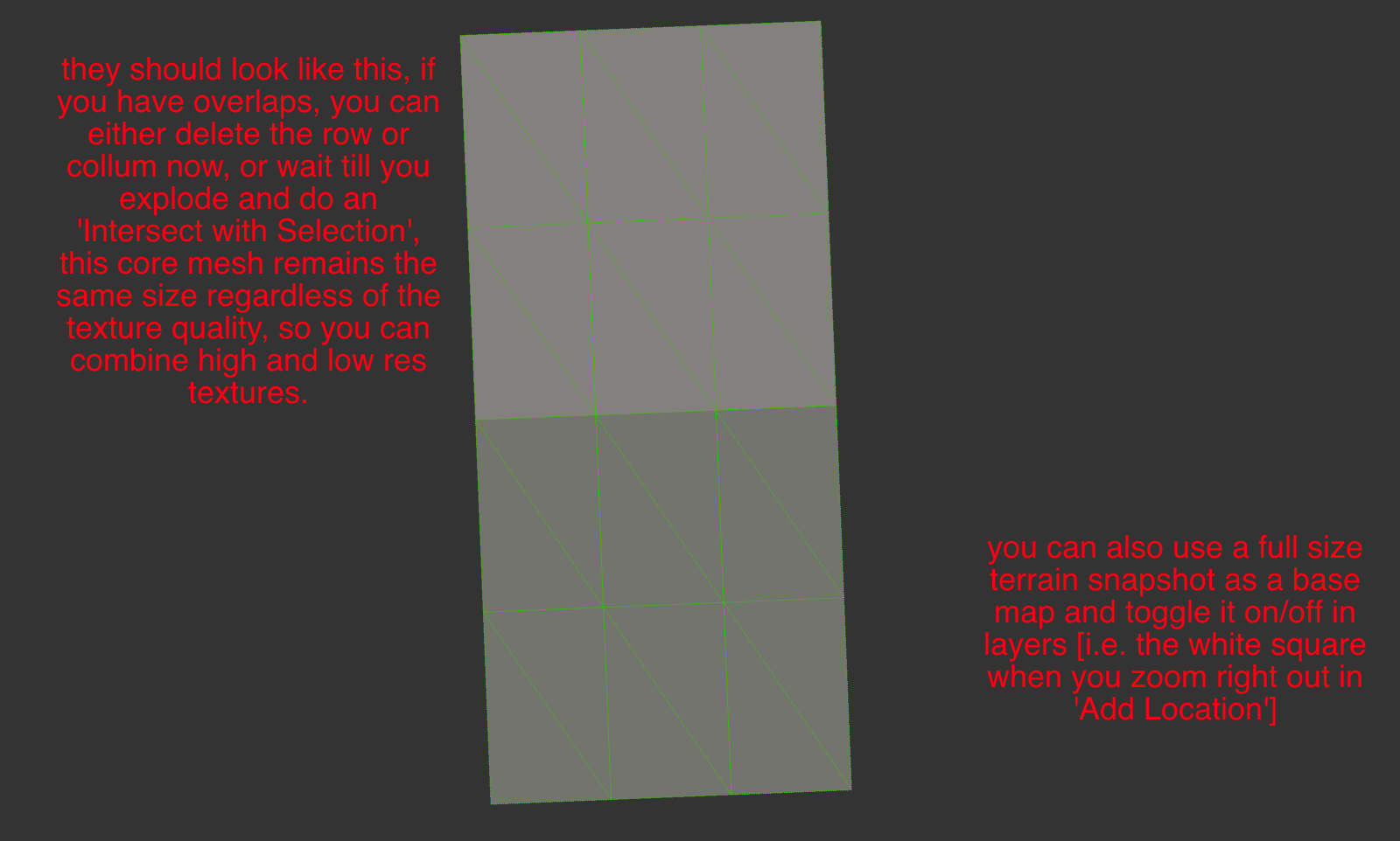
if you view an 'Add Location' 'Terrain' with 'Top View' [ON] + 'Parallel Projection' [ON]+ 'Hidden Geometry' [ON] + 'Face Style .. Shaded' you will see that the mesh is regular EXCEPT for the border.
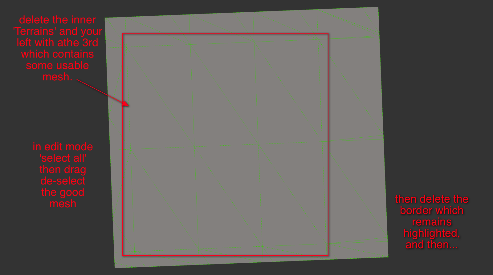
If you 'Unlock' this 'Terrain' then select all followed by alt/shift/selection-Box over the good mesh it will leave the borders selected for deletion.
The is under all the GE terrains, if you delete the borders, this good mesh will align with its neighbors.
A useful plugin only needs to 'Unlock Terrain' >> 'Select Borders' >> 'Delete Border Mesh'.
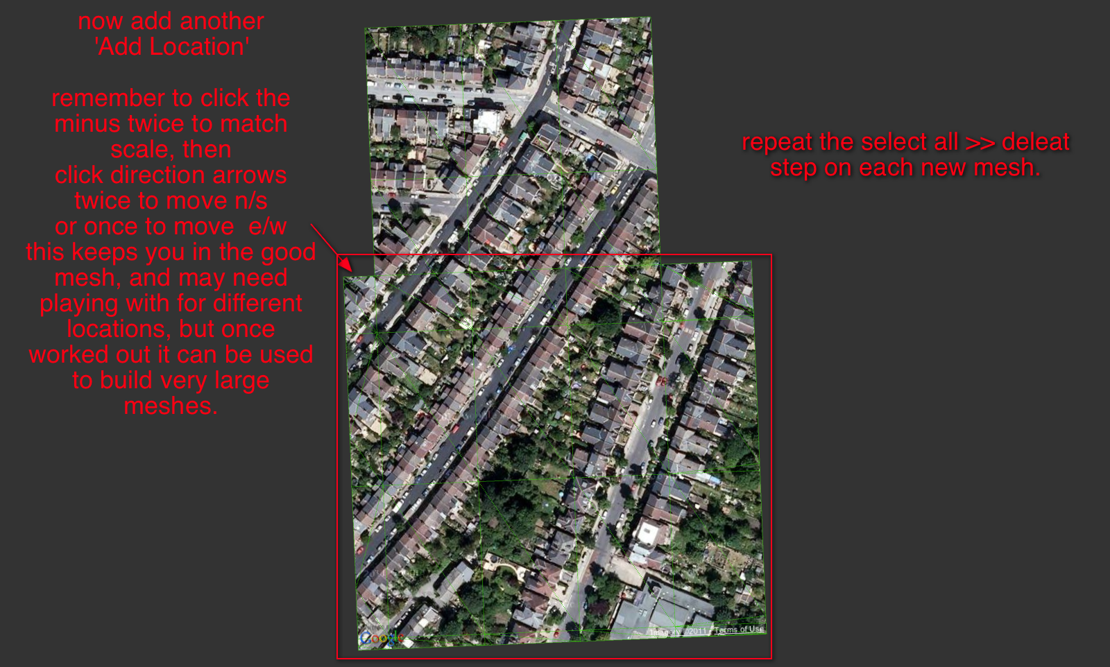
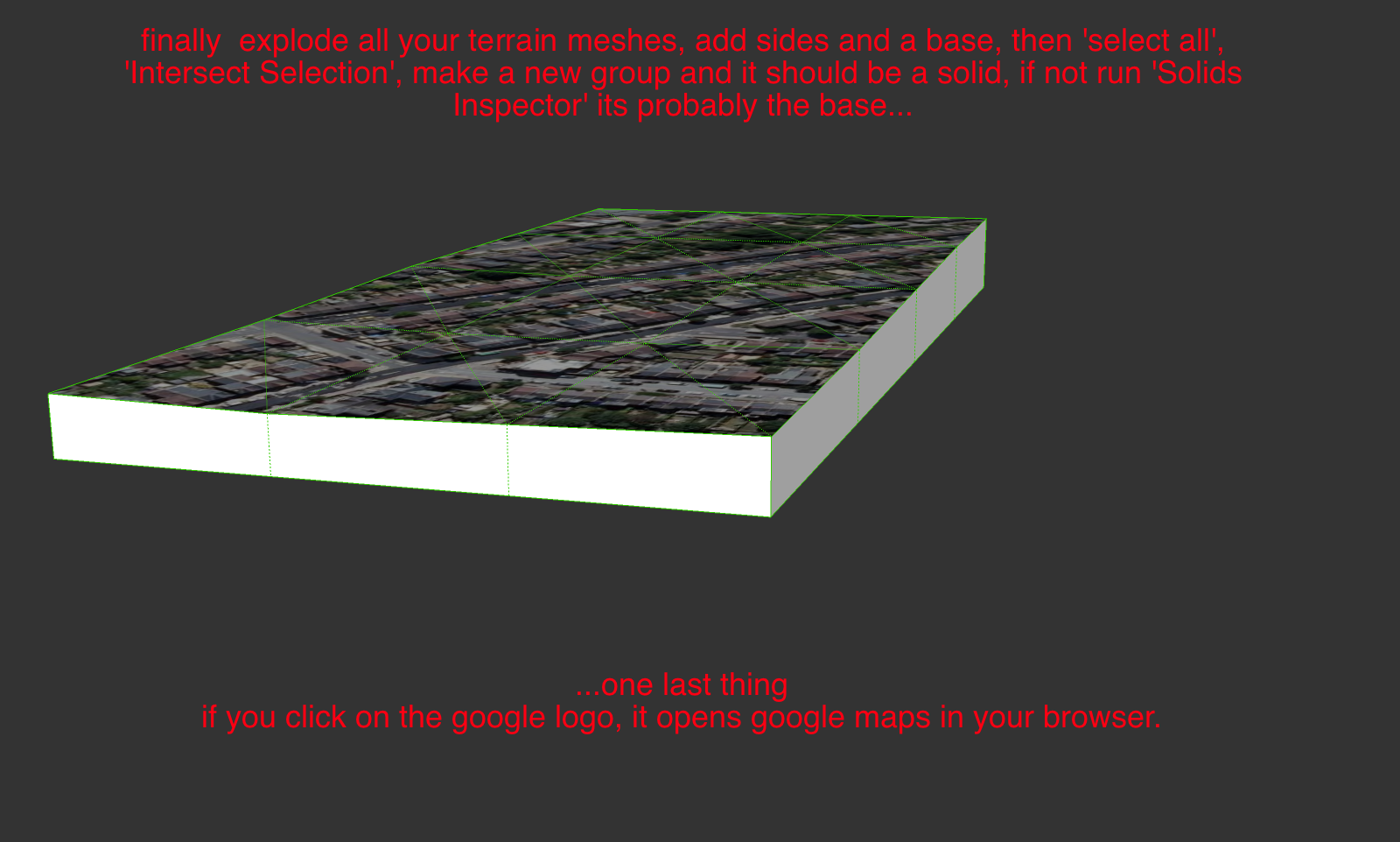
When you do this to a set of overlapping terrains they do mesh, but you can also delete the overlaps before exploding all into a new single mesh. I found I rarely needed to even intersect after this process.
I've got a half done tutorial if your interested.
john
-
the new version is working very well. The ability to change the order worked well and was definitly important (I made the test with two meshes in different resolutions... first time I tried, the higher res mesh was deleted... I reversed the order and was able to keep the higher res mesh. Even if I have to undo and redo the operation selecting the other option, its still like 1/10th of the time needed to manually ZORRO (use the Zorro plugin) to subtract one mesh from the other. Maybe 1/20th of the time!
Multiply that by 100 different meshes and you get a HUGE time gain!
Thanks a lot. Hope you find a solution to the small gaps betwen meshes, which can be weird when rendering a close-up animation.
if thats not possible I wonder if there is some plugin I can use to create some small cover for the gap? Like, joining the two meshes?
-
@driven said:
if you view an 'Add Location' 'Terrain' with 'Top View' [ON] + 'Parallel Projection' [ON]+ 'Hidden Geometry' [ON] + 'Face Style .. Shaded' you will see that the mesh is regular EXCEPT for the border.
If you 'Unlock' this 'Terrain' then select all followed by alt/shift/selection-Box over the good mesh it will leave the borders selected for deletion.
The is under all the GE terrains, if you delete the borders, this good mesh will align with its neighbors.
A useful plugin only needs to 'Unlock Terrain' >> 'Select Borders' >> 'Delete Border Mesh'.
When you do this to a set of overlapping terrains they do mesh, but you can also delete the overlaps before exploding all into a new single mesh. I found I rarely needed to even intersect after this process.
I've got a half done tutorial if your interested.
john
yes, I am interested John. I got a bit lost on your explanation, the tutorial would help.
-
@driven said:
I've got a half done tutorial if your interested.
john
Please do because I'm missing something in the process.
-
@AcesHigh and sdmitch,
I've been playing around with this [for the first time and I'm on a mac]
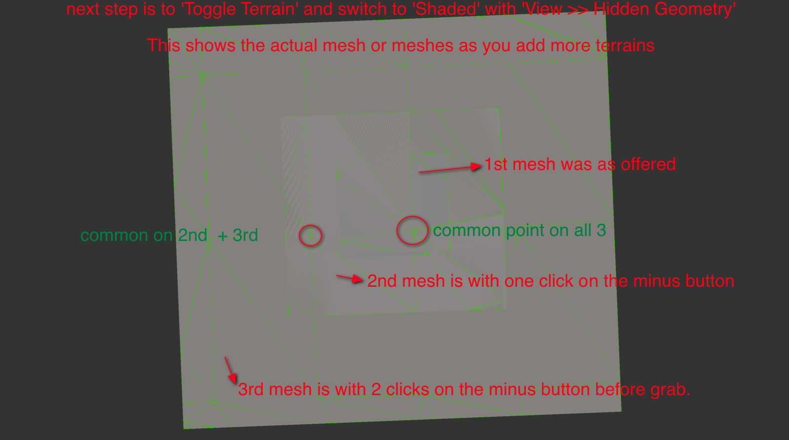
what I found is it's only the border set that are actually divergent. the spacing in the border is irregular [I suspect its to help flatten it for the 'Snapshot']I also found up to a point, the detail remains high even on large acreage, but falls back to triangulation if you go in too tight.
The short of it is I came up with a workflow that very repeatable here.
To start with
I have [ v ] as a shortcut key to toggle 'View >>Component Edit>>Hide Rest of Model'
and [ h ] as a shorthcut key to toggle 'View>>Hidden Geometry'
and [ u ] as a shorthcut key to 'Unlock'I set a new drawing to 'Top View' with 'Parallel Projection' and in 'Styles>>Edges>>Color All Same' >> 'Lime Green' on this one the backgrounds all 'Dark Grey'
I also open 'Layers' and put it to one side and for the tutorial 'Scenes' is open.
This is the Skp that I'm writing up notes for, but thought you may want a look in the mean time.
If you toggle between 'Shaded' and 'Shaded with Textures' on each scene, you'll probably figure out what I'm on about.
-
maybe someone with a good scene capture could make a better tutorial than this...
the skp is on the post before this one...
Using these steps a plugin that unlocks the terrain, then selects the irregular faces and deletes them would speed up the process.
Navigation for selecting the 'next terrain mesh' would be better if the html had an option to use last 'grab' as your starting point.
It does open on the last used but has 'no-cache' set and flicks to the stored model location as the starting point.
It's a server-side script so can't be tweaked...Maybe a feature request is called for...
john -
Apparently there are major differences between the Mac and Windows versions. There is no border, that I can find, that is left when the mesh is de-selected.
-
Hi,
can't be thatdifferent, so it's probably badly explained [by me]
can you erase the outer mesh, with the 'eraser tool'?
maybe someone one a PC can interpret my explanation.
I'll try on a PC tomorrow.
john
-
Maybe I've finally figured it out. By border, did you mean a border of a row/column of cells?
-
@sdmitch said:
By border, did you mean a border of a row/column of cells?
Yes, the perimeter rows and columns of faces and edges, is all that's distorted.
I thought it must be my chose of words
I was just about to fire up XP, please tell me that's not required.
[to me it's a barbaric form of punishment]
john
-
No, you can avoid the torture if you like.
-
Sdmitch, sorry if I am talking nonsense, specially since I dont even know the method you used in your plugin.
anyway, maybe you can just do an "automatic" way of doing what I did manually?
basically:
we have two different meshes

view them from top, parallel camera

use Zorro plugin (I dont know if you can use the code of another plugin) and CUT one mesh from the other. The Zorro cut line should follow the edge lines of the other mesh. IF its difficult using the Terrain Mesh as a basis for the CUT LINES, maybe its possible to use the SNAPSHOT (which are flat surfaces) edge lines as a basis for cutting the mesh with Zorro? Then delete what was cut from the mesh.

-
If the two meshes are the same scale,ie grabed with the same zoom, the grids should be the same size and origin. Then you only need to delete the outer row/col in the overlap area as per John's procedure. I have successfully ran several test using John's procedure and the results is seamless.
-
@sdmitch said:
If the two meshes are the same scale,ie grabed with the same zoom, the grids should be the same size and origin. Then you only need to delete the outer row/col in the overlap area as per John's procedure. I have successfully ran several test using John's procedure and the results is seamless.
well, but thats one problem. The meshes hardly will be the same zoom...
specially if you want to add a very large area, for distant background (like mountains, hills), and a smaller area, with detail, where you will render the image/movie. -
if all else fails, a plugin that culd transform a mesh into a solid would be awesome already. IF we could transform a mesh into a solid easily, it would also be pretty easy to perform Boolean operations (using the Solid Tools from SKP8 or OSCoolean plugin)and get the desired result.
-
@jolran said:
Maybe you could build a box "underneath" the surface and do standard boolean on that?
maybe I am doing something wrong, but I just cant build the box underneath the surface. I draw the lines but they do not create the faces of the box.
-
@aceshigh said:
if all else fails, a plugin that culd transform a mesh into a solid would be awesome already. IF we could transform a mesh into a solid easily, it would also be pretty easy to perform Boolean operations (using the Solid Tools from SKP8 or OSCoolean plugin)and get the desired result.
actually, turning the meshes into solids and then making boolean operations are maybe not the best solution. Just did that (through a too complicated process that would take days and days to perform if I had hundreds of meshes*) and when I had the two solids out of the meshes, I tried to perform a boolean and got a BUGSPLAT!

I can only imagine how many bugsplats I would get when trying to do 100 different booleans out of complicated solid meshes in the same model

*basically, I drew a rectangle underneath the mesh, the selected only the mesh edges and used TIG´s Extrede Edges By Vector, and then intersected the extruded edges with the rectangle.
deleted the rectangle then deleted all the faces BELOW the rectangle, then the lines...
-
@sdmitch said:
If the two meshes are the same scale,ie grabed with the same zoom, the grids should be the same size and origin. Then you only need to delete the outer row/col in the overlap area as per John's procedure. I have successfully ran several test using John's procedure and the results is seamless.
To add to this, I have only found one grid size, if a mesh is smaller, it's a 'border region' row or column.
mesh is same size, except the colored bordersThere is a fixed Maximium size of grid for a single 'grab', which makes stitching much easier.
There are at least two levels of detail, but you can manipulate which you want, and you can mix and match if you use two drawings or re-naming.
So to get into High Resolution Large Format mode you need to
- go to your basic location
- click to zoom in or out until see your largest 'grab' option, it's a big white square border.
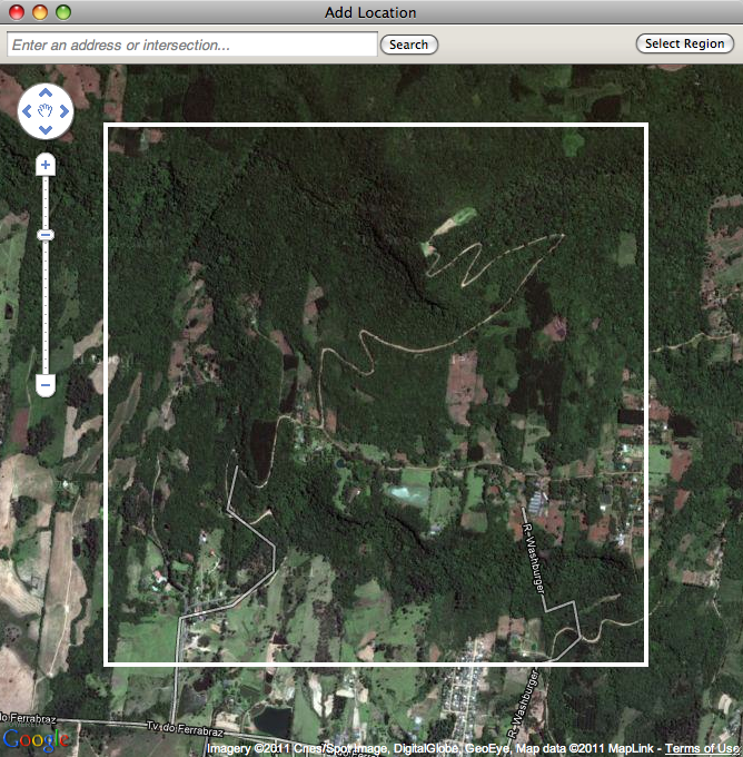
3.for Lowest Resolution just 'grab' the lot and cut up what you want. for 'HRLF' center the square and click in as far as allowed [seems to be 4 clicks] - NOW the trick, open 'Model Info' >> 'Geo'Location' and select 'Clear Location' and clear it.
- Go Back to 'Add Location' and 'grab', this will reset your Geo Location at the finest detail.

- Go Back to 'Add Location' and click out until you see the white border again, and 'grab' [this is the largest square at the highest resolution available].
- If you want neighbouring blocks at 'HRLF' repeat 6, but before the 'grab' also click N, S, E or W, a couple of clicks or move manually.
- unlock and delete the 'border region' rows or columns and stitch together.

a ruby to unlock, select and delete these would help, [but it's quick anyway].
john


Advertisement