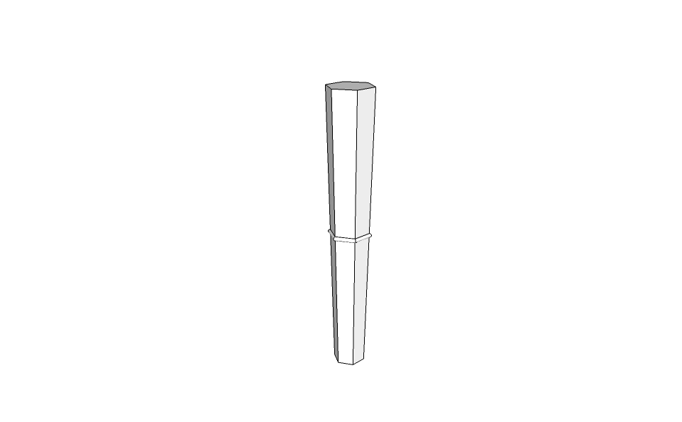
Extruding on a tapered polygon.
-
This is what I get, doing it my way. I will try your way. Thanks.
BTW - I don't know whether my attachment will go with this message - how do you attach models to these posts?
Meltapered leg 2.skp -
I was thinking more like this. Starting with a 4 inch polygon...moving to 36" blue...resize to 6"...create one surface parallel to an axis...locate the 1/2" bead location...draw 1/2" bead in the center of the surface...create the other surfaces...draw one edge of the bead on the other surfaces...follow me. follow me?
-
SU likes profiles started and ended on perpendicular surfaces. Try it starting your follow me in the center of a surface.
-
Mel, your model uploaded fine and it shows exactly what I would expect of Follow Me when run as you did.
The way I illustrated works perfectly however.
Good work mics_54 but he wants a cove not a bead.

-
-
Or a reverse bead.

-
Oh a cove. OK I'll butt out..too many cooks etc. etc.
-
@dedmin said:
Great help...thanks. Let ME try that now! I think it will take me more than 50 seconds.
-
SUCCESS...look Mom, I did it!! Thanks for everyone's help.
Now, I have another question (this one should be simple, but I can't find an understandable answer in any of the tutorials or manuals...how do I draw a finite guide line on the face of a surface (like on all the faces of the tapered leg WE just made)? All I seem to get is guidelines that run from left to right into infinity.
Thanks again...I am slowly getting the hang of this.
Mel
-
Good work.
You can draw a finite guideline by dragging from a point. The guideline will end in a guidepoint. Is there a reason you need a finite guideline?
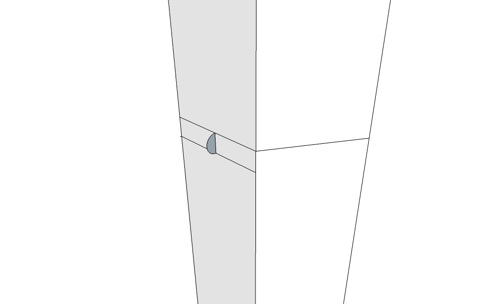
FWIW, dedmin's method works but isn't strictly accurate. The profile isn't drawn perpendicular to the first leg of the Follow Me path so it results in a cove that is not cylindrical. In this application that isn't likely to be a problem nor will it be noticeable. If this was something for which you were going to end up creating a template to trace or something along those lines, starting the with the profile not perpendicular could be problematic.
-
@dave r said:
Good work.
You can draw a finite guideline by dragging from a point. The guideline will end in a guidepoint. Is there a reason you need a finite guideline?
It doesn't seem to work for me...The line always goes perpendicular to where I want it to be. I have tried toggling the CTRL key, but that doesn't help. I have tried holding down the left button on the mouse, and that doesn't help either.
The reason I would like to learn this is for positioning "things" on the face of a tapered surface, etc. Maybe it's not important, but now I am annoyed I can't do it! It worked ONCE for me, but I can't seem to figure out why.
Thanks. If not, I can probably live without it. -
Watch for a PM in a moment.
-
-
Very good Jean.
Sometimes it would make sense to go back and start drawing the whole thing over rather than trying to modify what you've already drawn. Follow Me on the whole profile would be quick and easy. As with dedmin's method of adding in the profile at the corner, the result of starting the profile at a corner will result in the groove's shape being modified from the semi-circular profile to an elliptical shape. No one would be able to tell that by looking at the model so it would be of little consequence but there may be times when that would be important to remember.
-
Hi Dave, hi folks.
You are rigth. The "Follow me" Tool first operation is to rotate any profile that is not perpendicular to the start of the path in such a way that it becomes perpendicular. the only problem is that it is not really a rotation but a projection. In this case of a circular groove, it will, indeed, becomes elliptical.
In my example, I just drew a circle centered on the midpoint of the slanted side and then I erased the unwanted part to get a circular grove. A more refined method would be to carefully position this "cutting" circle to mimick, as well as possible, the positioning of a real life router bit.
Another possibility would be to carefully position a cylinder on one side of the leg, then do an intersection and finally delete unwanted geometry. After that, a circular array can be made with the grooved face to obtain 5 more. This would work but is a lot of work.
Just ideas.
-
@jean lemire said:
Hi Dave, hi folks.
You are rigth. The "Follow me" Tool first operation is to rotate any profile that is not perpendicular to the start of the path in such a way that it becomes perpendicular. the only problem is that it is not really a rotation but a projection. In this case of a circular groove, it will, indeed, becomes elliptical.
In my example, I just drew a circle centered on the midpoint of the slanted side and then I erased the unwanted part to get a circular grove. A more refined method would be to carefully position this "cutting" circle to mimick, as well as possible, the positioning of a real life router bit.
Another possibility would be to carefully position a cylinder on one side of the leg, then do an intersection and finally delete unwanted geometry. After that, a circular array can be made with the grooved face to obtain 5 more. This would work but is a lot of work.
Just ideas.
Hi Jean,
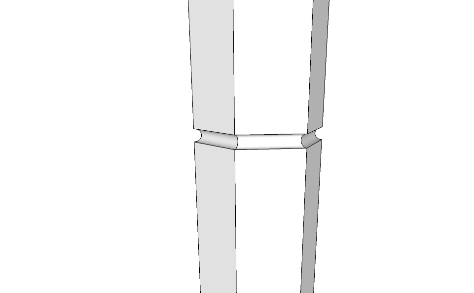
I think I did it your way this evening (this SU can become addictive, I am learning). I made a tapered leg and then realigned the axes for each face before I drew a vertical bead up the side of the leg using the push/pull tool. It seems to have worked quite well. I had to do a little cleanup at the top of each leg, but that wasn't hard.
Thank you (everyone) for your help.
I shall be back!!
Mel
Hello! It looks like you're interested in this conversation, but you don't have an account yet.
Getting fed up of having to scroll through the same posts each visit? When you register for an account, you'll always come back to exactly where you were before, and choose to be notified of new replies (either via email, or push notification). You'll also be able to save bookmarks and upvote posts to show your appreciation to other community members.
With your input, this post could be even better 💗
Register Login


Advertisement