Skewed Paneling
-
Hi all,
I've been following this forum for a while in the background and finally called up enough courage to ask a question. I run a custom woodworking shop where we build just about anything designers and clients ask for; anything from casework and furniture to paneling and doors.
I'm a very visual guy and find it helpful to lay everything out in SketchUp before proceeding with the build. It also adds a bit of the 'wow' factor to the client who comes in with a napkin drawing to see their item to scale and in three dimensions weeks before they actually get to touch it.
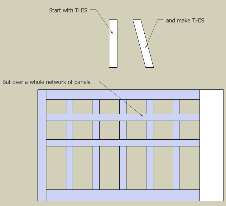
I'm a little stuck on this one, though. It is to match existing paneling in an old house under a stairway. I've been able to mock up most of the paneling except for the bit that fits under the pesky staircase. The paneling, as a whole, is skewed to the left about 45* or so. Is it possible to draw the paneling as if it were all at right angles and then skew the whole group to fit this area? If I'm not making any sense, please say so and I'd be happy to elaborate.
I've attached a picture. I hope it works.
Thanks for any help.
best,
cb
-
Hi Charles,
I'm not a woodworker but to me it seems that either by selecting the top edge (face if 3D) and moving it to left or the bottom one to the right would do the trick. If you first make it into a component,place it vertically all around and after that doing it while editing the component, should "pop" each piece into its place and shape at once.
-
Charles,
I don't think you can do what you want while leaving the individual parts as components. However, as Gai wrote, you could skew the components by selecting an end face and its edges and using the Move tool. Keep in mind that if you've drawn the piece of wood to its final width, skewing it will result in it being narrowed. It won't be the same as mitering the ends and rotating the component. The other thing to consider is that by skewing the component, you'll increase the dimensions of the bounding box. If you want to get a cutlist from the components, you'll end up with some incorrect numbers.
If I were doing this I would draw the pieces with mitered ends and then use the Linear Array function of the Move tool to copy the components as needed. Then I would make them unigue and edit their length as needed.
-
@dave r said:
...Keep in mind that if you've drawn the piece of wood to its final width, skewing it will result in it being narrowed. It won't be the same as mitering the ends and rotating the component. The other thing to consider is that... If you want to get a cutlist from the components, you'll end up with some incorrect numbers...
Oh well,true, very true. Things a non-woodworker doesn't think about first.
-
Some woodowrkers might not think of it either.

-
Thank you for the quick responses. Gaieus, I tried doing something similar to that. Unfortunately, it did just as DaveR said it would and changed the overall width of my stiles and making a cutlist has now become much more difficult.
I guess I was looking for something quick and easy when, obviously, quick and easy is never the best solution.
DaveR, I'll give that a today when I get out of the shop. Our customer gave us the old panels from which we've gleaned some information but they're in pretty rough shape (water damage over many, many years). I'll see if I can guess the mitre angle and hopefully things will work from there. I cannot tell you enough how I'm not looking forward to putting mitred rails through our shaper. Oh, and as a side note, Dave, thank you for the wonderful work you produce over at your FWW blog. I've enjoyed following the instruction both you and Mr. Killen have been able to provide.
I shall keep you posted as to my progress.
-
Charles, I'll be interested to see how it turns out. Perhaps you can take some photos and include them with your SU views.
You might find it easier to measure a rise over run sort of thing instead of trying to get accurate angles. You can enter angles as x:y instead of an angle if you wish.
Thank ytou for the kind words regarding the blog. I'm glad you find it helpful.
Dave
-
James, that is good. What do you do then for the width of the panels? For example if each piece is to be 600mm wide, do you do the math first to figure out how wide to draw the piece so that after skewing, it is the correct width? Or do you resize the component afterward?
Here's another way.

Draw the panel element. Make it a component.

Rotate the component to the required angle. Make a linear array to cover the distance.

Miter the ends. I selected the edge at the high corner and used Move to bring it down to the top of the panel.

All of the components get the same treatment.

Repeat for the bottom.

For those components that need to be mitered for the left and right edges select them individually, choose Make Unique from the context menu. Trace along the edge of the frame and use Push/Pull to delete the waste.

Paneling is complete, each board is the desired width and the bounding box is properly aligned to yield the correct information in a CutList. The axis alignment also makes it easi to add wood grain materials if desired.
Hello! It looks like you're interested in this conversation, but you don't have an account yet.
Getting fed up of having to scroll through the same posts each visit? When you register for an account, you'll always come back to exactly where you were before, and choose to be notified of new replies (either via email, or push notification). You'll also be able to save bookmarks and upvote posts to show your appreciation to other community members.
With your input, this post could be even better 💗
Register Login


Advertisement