Lathe Stand Legs
-
It's kind of close to woodworking.

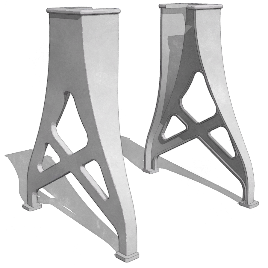
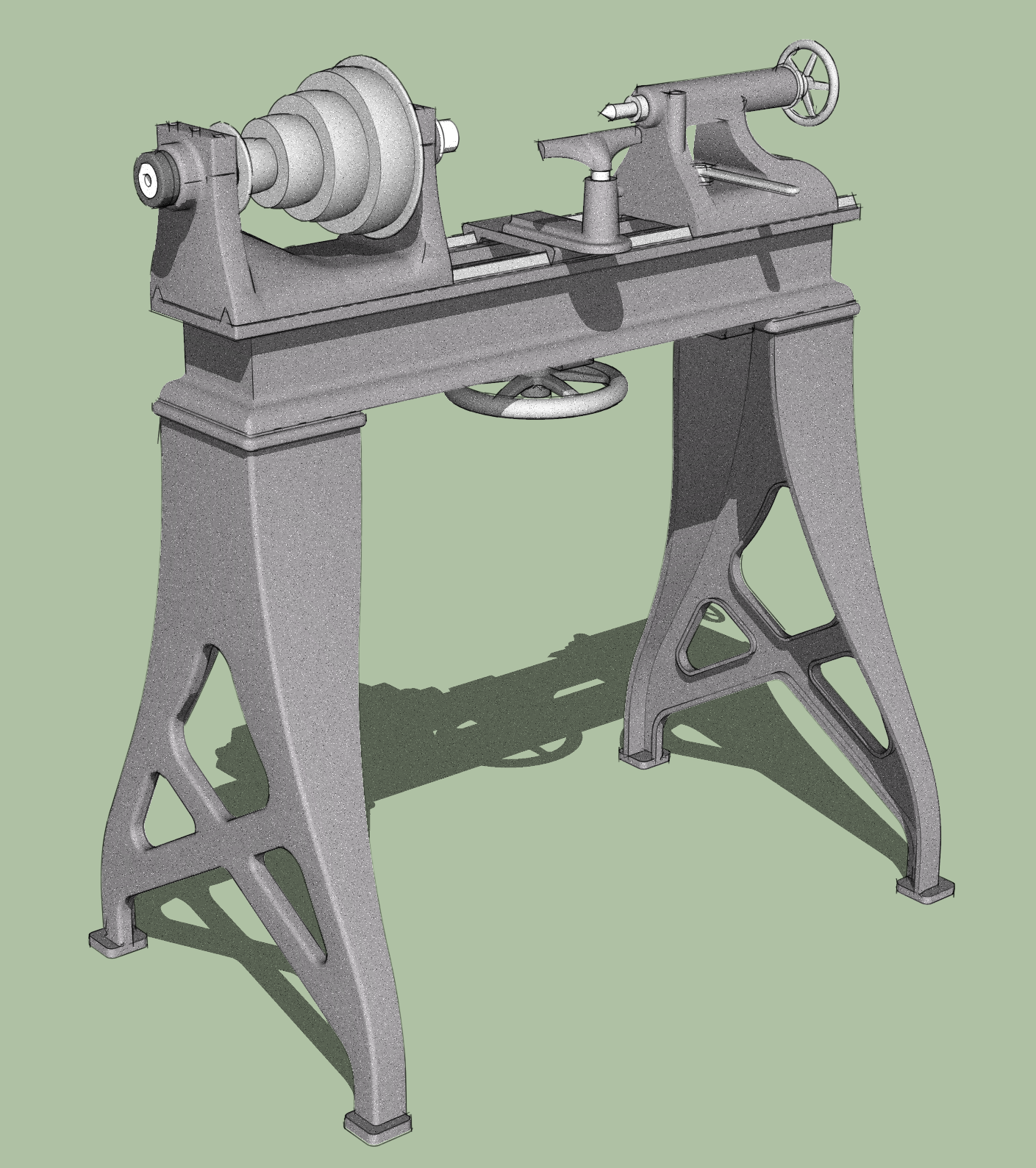
I found dimensioned drawings for these cast iron lathe stand legs in an ancient text book on mechanical drafting and thought I'd give them a shot. There were drawings for other parts of the lathe and I might have to model them to see if I can come up with a whole lathe model. It's designed to run on an overhead line shaft and the head stock has four different sized pulleys for the wide leather belt.
-
Ahhh... the good old days when even utilitarian objects had beauty ! Great job
 .
. -
 Dave,
Dave,
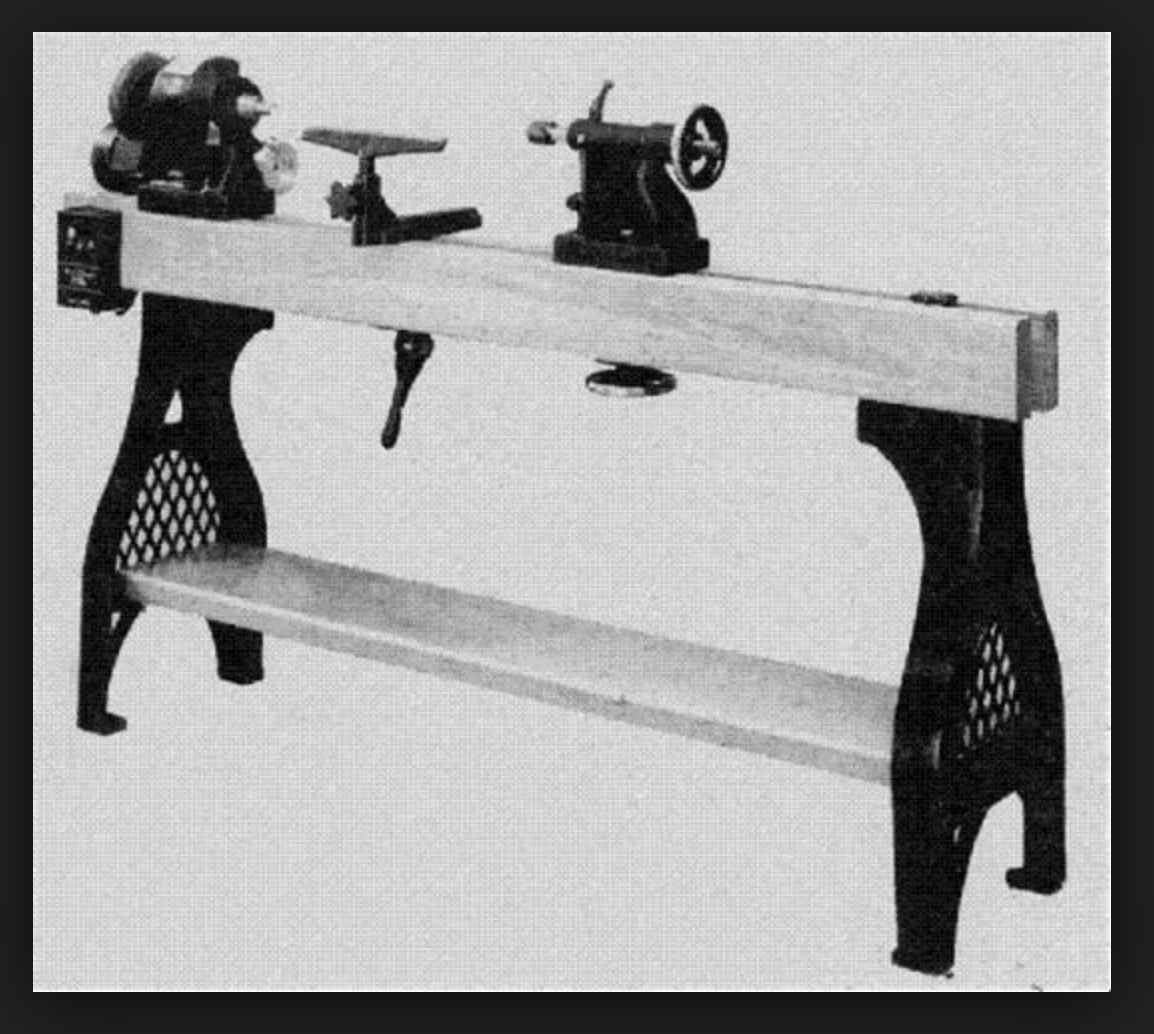
Now that you've done some warm-up, maybe you can model a Conover Lathe. Created by noted woodturner Ernie Conover and his father, the lathe was made for a good 20 years, up to the 1990s. It had cast-iron legs, banjo, and tailstock, and hardwood ways. You can still find some for sale here and there. I could probably get Ernie to provide a better image.
Best,
dh -
Maybe for the next lathe David. That's a good idea. I wonder if Ernie has measured drawings for the parts and if he'd share them with me.
I found drawings for the rest of the lathe my legs go to. I think I'll model it up completely and see if I can get it 3D printed at 1/4 scale or something.
-
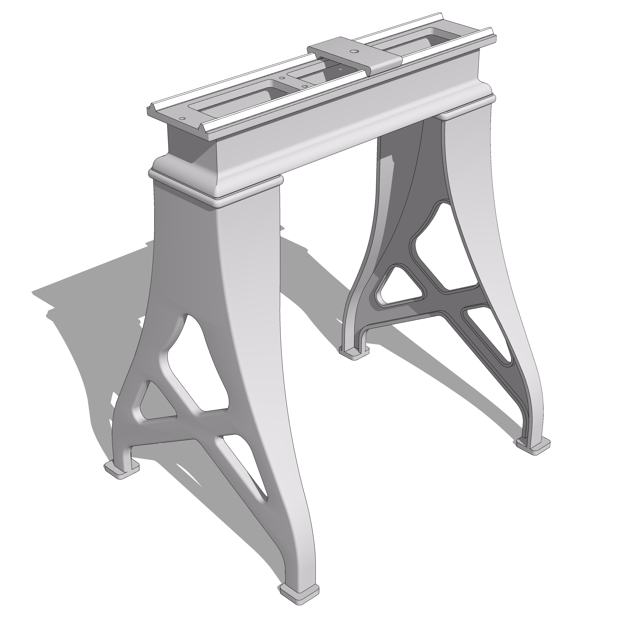
Added the bed and the top half of the banjo clamp. The drawings I'm working from don't indicate the overall length of the bed but that will be easily changed later. Leaving it short for now makes it easier to work on the parts that have to go on it.
-
Nice. But odd that the banjo clamp rides on those rails and so can't move laterally. I'll bet this was a lathe for making furniture parts.
-
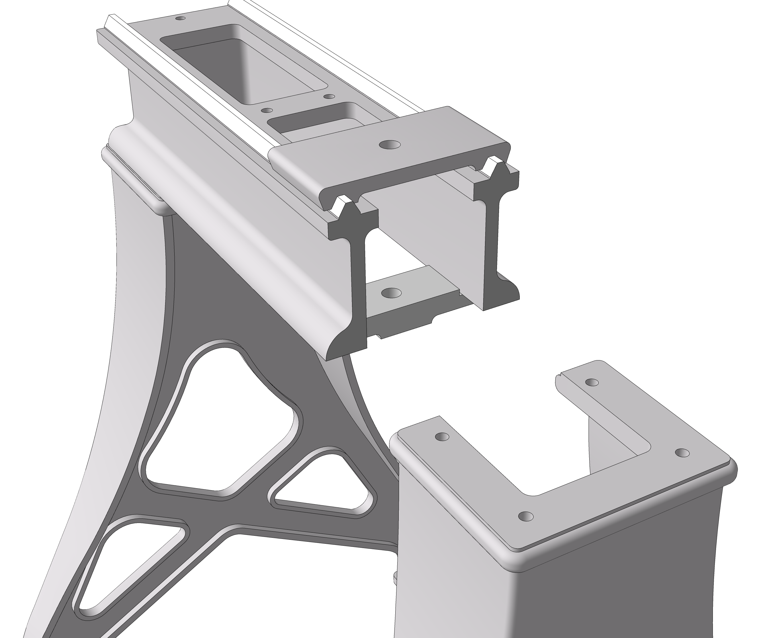
The banjo itself has a T-slot on its underside that goes over the square head of a bolt passing through the top and bottom halves of the clamp. That allows the banjo to slide in and out and be rotated. There's a hand wheel threaded on to the bolt from below which can be loosened to allow the assembly to slide along the ways.
-
This shows the bottom clamp jaw for the banjo mount in place.
-
Simply beautiful!
-
Added the banjo for the tool rest and the bolt that clamps it in place. Still need to thread the bolt and add the hand wheel along with the tool rest and its locking screw.
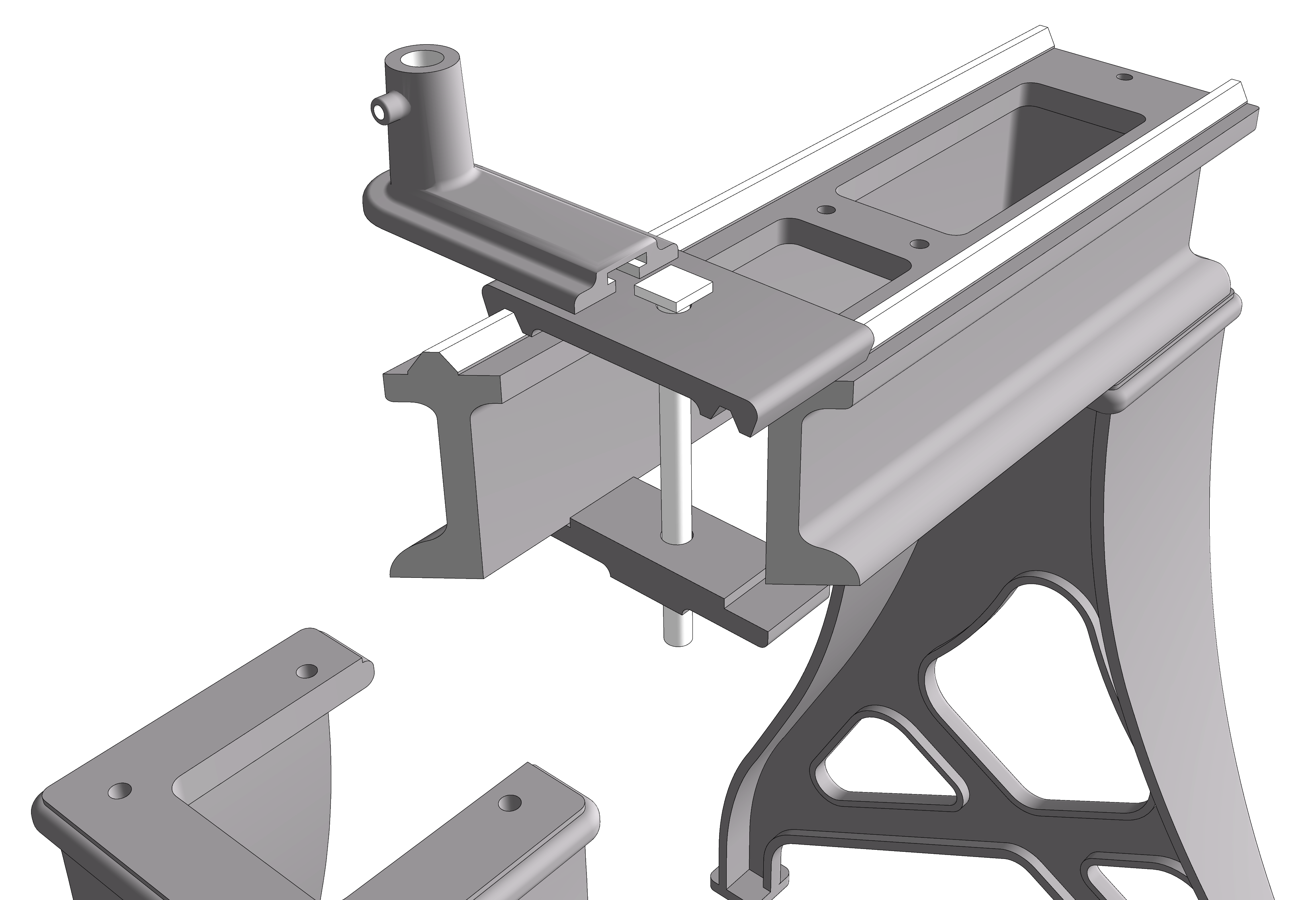
The biggest challenge in modeling any of this so far has been figuring out how the fillet around the tool post holder should run out where it meets the radius on the narrow part of the base. Got it in the end, though.
-
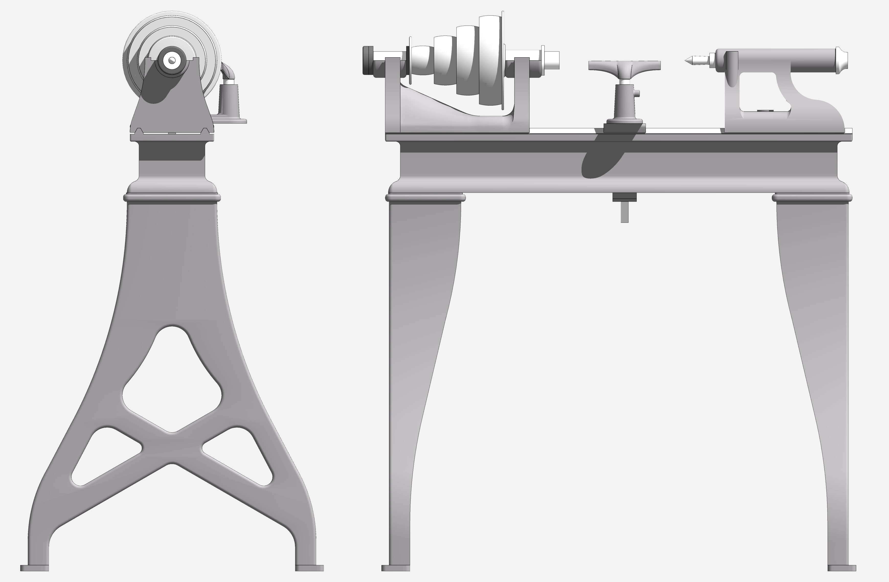
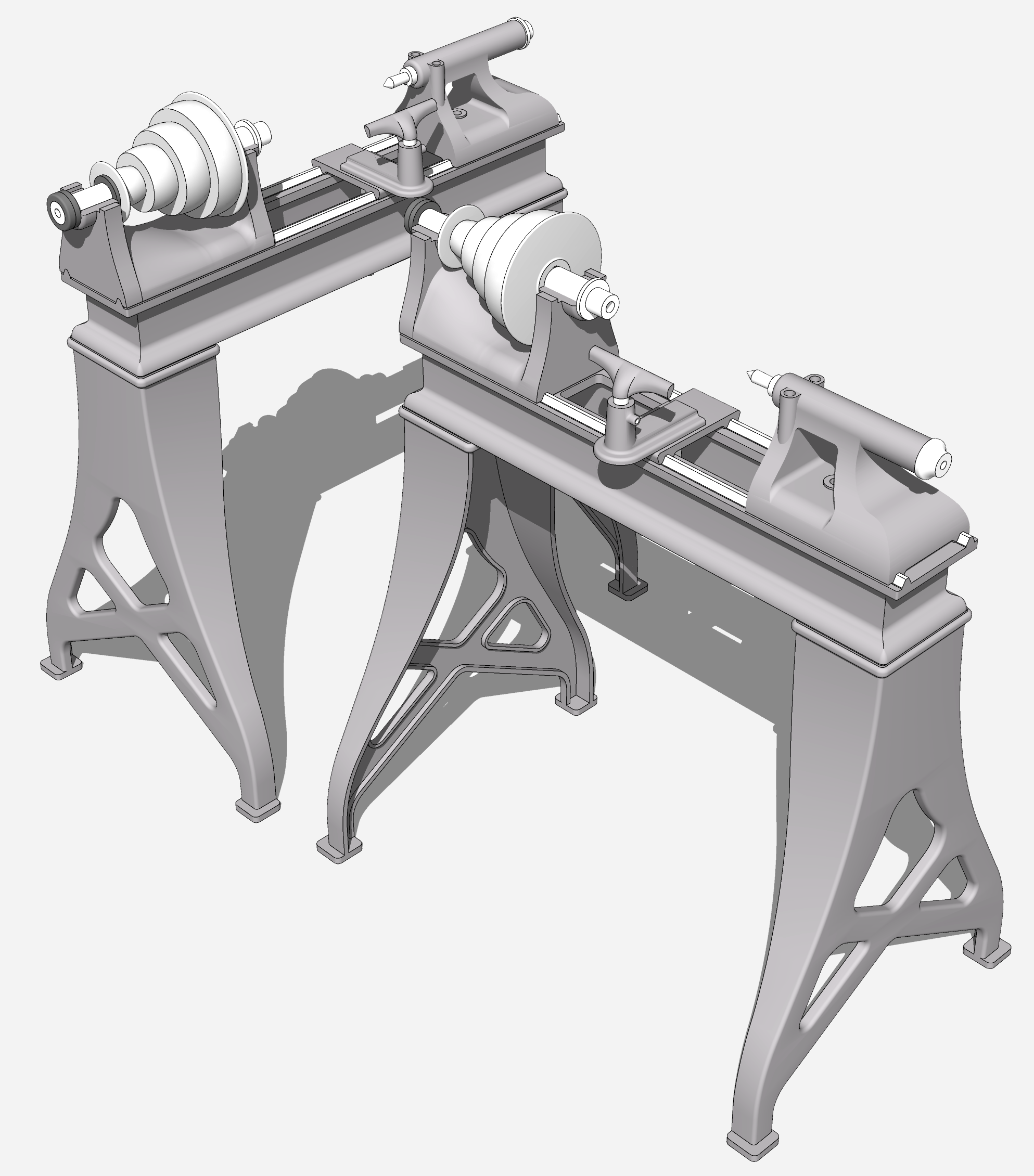
-
Brilliant! I love the model, nice work!
-
Wow. Great job.
It's probably a good thing that the lathe doesn't have it's own motor. You'd probably want to model all the copper windings.
-
Thank you gentlemen.
David, I am trying to decide where to quit adding detail. The screws threads on the various parts are calling to me.
 As for power, I'm wondering if I can add the belt and the driving wheel above and have them sort of float above the lathe.
It would be cool to get this 3D printed in metal but I imagine a real full size lathe would be less costly.
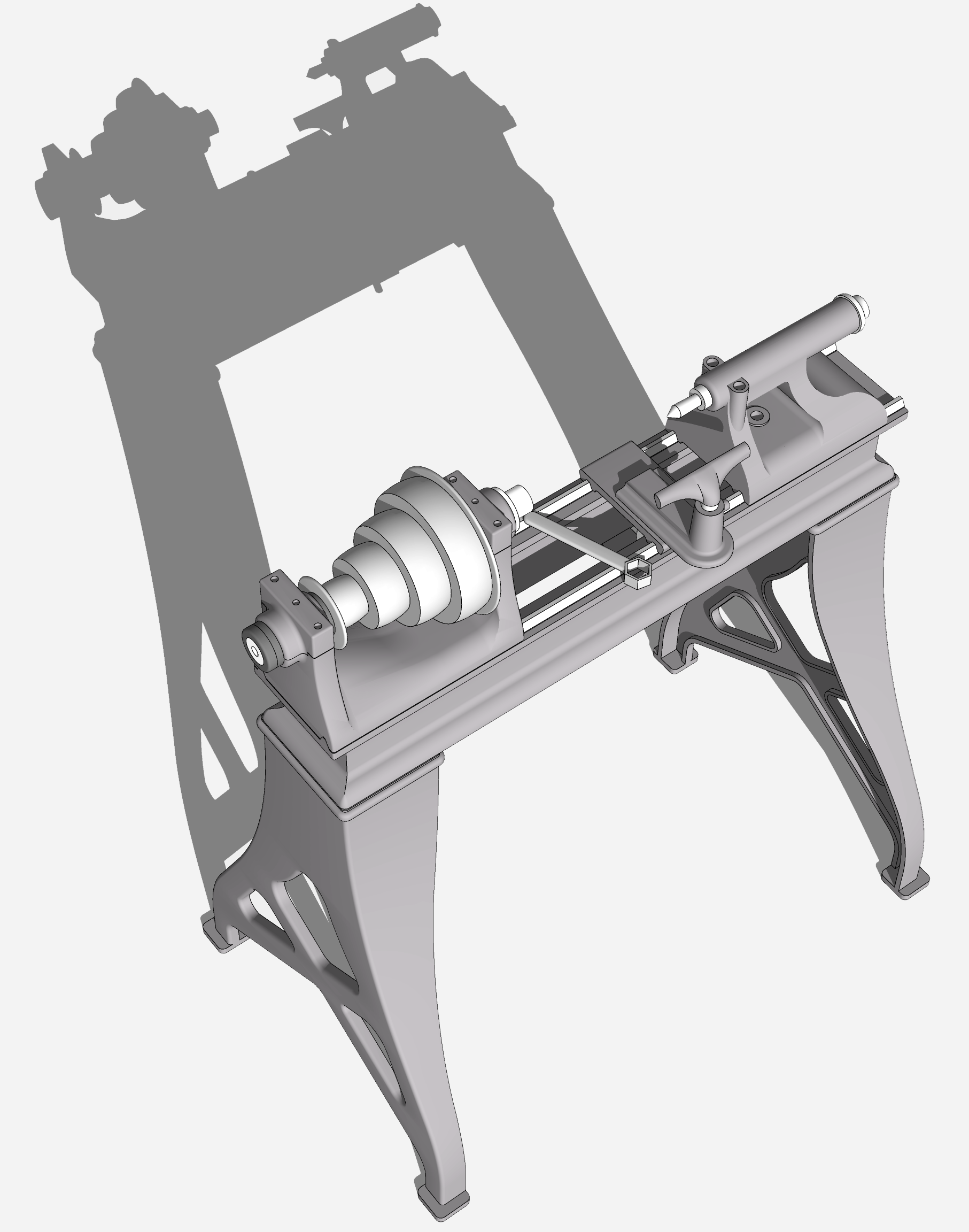
-
Step away from the screw threads, sir.
However, you might want to model a #2 Morse taper in the headstock and tailstock, and add a handwheel to advance the tailstock.
I like the idea of adding a belt and wheel over the lathe.FWIW,there used to be an amazing woodturning shop in Philadelphia's Old Town: The John Grass woodturning studio. The Center for Art in Wood, which promotes woodturning and sculpture, tried mightily to save the studio but was ultimately unsuccessful. John Grass was the oldest woodturning shop in Philly, dating to the mid-19th century. Among many other things, John Grass turned all the billyclubs that the Philadelphia P.D. used. The turning studio had two floors of machinery--planers, jointers, saws, and woodturning stations. These were long benches with a headstock and a tailstock bolted to the benchtop at various intervals. Everything in the shop was belt-driven, powererd by a 5-hp motor in the basement. The motor made a fearsome racket when it was turned on, and the belts also put out quite a noise as they spun and slapped. All of this is to say that parts of the lathe that Dave R. has so beautifully modeled might have been used in one of those wodturning stations.
-

@davidheim1 said:
However, you might want to model a #2 Morse taper in the headstock and tailstock...
The #2 Morse tapers are in there already. I added those when I drew the parts that have them.
@davidheim1 said:
...and add a handwheel to advance the tailstock.
Hand wheels are next. There's one for the tail stock and another under the bed on the bolt for the tool rest.
@davidheim1 said:
I like the idea of adding a belt and wheel over the lathe.
I'm thinking about modeling only half the belt and maybe omitting the wheel up above.
@davidheim1 said:
FWIW,there used to be an amazing woodturning shop in Philadelphia's Old Town: The John Grass woodturning studio. The Center for Art in Wood, which promotes woodturning and sculpture, tried mightily to save the studio but was ultimately unsuccessful. John Grass was the oldest woodturning shop in Philly, dating to the mid-19th century. Among many other things, John Grass turned all the billyclubs that the Philadelphia P.D. used. The turning studio had two floors of machinery--planers, jointers, saws, and woodturning stations. These were long benches with a headstock and a tailstock bolted to the benchtop at various intervals. Everything in the shop was belt-driven, powererd by a 5-hp motor in the basement. The motor made a fearsome racket when it was turned on, and the belts also put out quite a noise as they spun and slapped. All of this is to say that parts of the lathe that Dave R. has so beautifully modeled might have been used in one of those wodturning stations.
That would be interesting to see. I've been to the Hadley Museum and in the machine shop there. I'm hoping to visit a steam powered machine shop in south central NY this summer.
-
My memory failed me in a couple of details about the John Grass woodturning company (not woodturning studio). It used a 7.5 hp motor, not a 5-hp, and the motor replaced a steam engine.
-
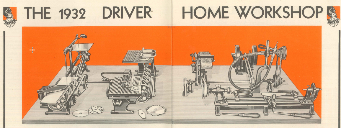
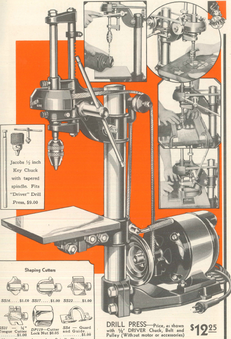
I expect since electric motors got smaller and more affordable, shop safety increased. I have my father's 1932 Walker Turner benchtop drill press. It was originally intended to be run off a line shaft that was mounted parallel to the long dimension of the bench. One motor underneath and tools arrayed along the length of the bench with belts going to pulleys on the shaft. The drill press could also mount the motor on the base. Fortunately my father reworked the DP so it has its own motor mounted upon the back so it has a reasonable belt arrangement.
-
A tiny bit of progress.
-
Rookie mistake, look at all those reversed faces.

Advertisement


