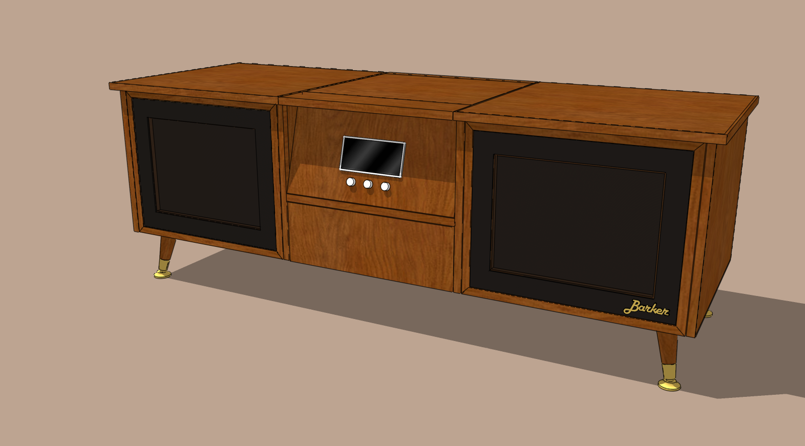
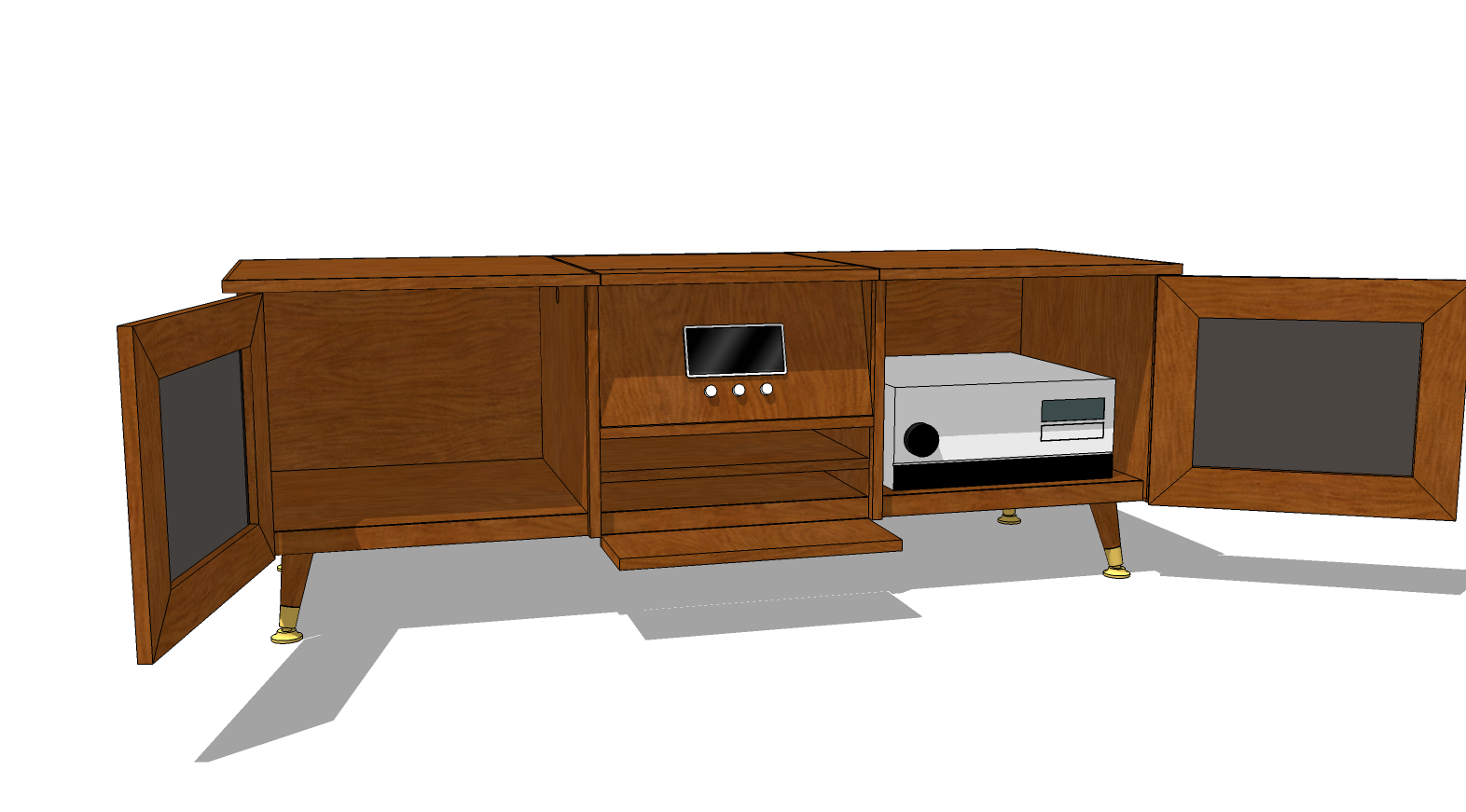
My first woodworking project
-
Thanks gents,
Pilou, like Dave said, dynamic components provide the animation. They can be activated in the free version of Sketchup but unfortunately they can only be created in the Pro version.
Dave, whoa, thanks for the thoughts. It's going to be hard to convince me to go away from the manual crank, but I hadn't considered the material for it. How to lock the projector into position is something I still need to figure out.
I do plan on utilising the knobs as power and volume controls. Might even have a small touchscreen, but more likely to harvest an old radio display.
The front is shown to hinge right down so that I can use the keyboard when the remote doesn't cut it. But I had planned on it just tilting out about 20mm when the rotation of the projector contacted and forced it and then tilting back by gravity.
I'm clearly going to have to do some serious research into the terms that you are using, but thanks for all of the info, I expect it will save me heaps of time. As for the draw, it was a bit of an afterthought to firstly support the hinged down top if I want to use the keyboard and also to house remotes and the occasional DVD, but I tend to agree with you, it is very shallow, if there is a neat alternative to stop the hinge front from over-hinging then, let me know.
Finally, sorry about my building methods. I normally build factories and equipment where I don't have to pull the whole thing apart into pieces once I'm done. Before I go too much further I will change them all into components. I guess it makes sense from a part list point of view (I assume that's what you mean?).
Thanks again.
-
I like your idea of letting gravity hold the front panel in place. I envision a sort of cam arrangement on the rotating part that pushes the front panel out and then perhaps springs to keep it tight against the cam.
As to the component thing, part of it is for making a sensible material list but it's also to make the model easier to edit. For example I would make the side top panels copies of the same component with one of them flipped (mirrored) relative to the other. The same for the case sides, doors and internal dividers. That way, when you edit one copy, the counterpart also gets edited. this reduces the amount of work that would go into modifying the model and reduce the chance for errors. If you are going to go with the crank arrangement you'll need to put a hole in the right side but leave that until near the end so you can make all the other required changes.
This sounds like a good learning experience for you in the shop. What sort of tools do you have access to?
-
It's that i have presumed when I saw the opening doors but want to be sure for the complex rotation!

Why dynmic components are not more used for crazzy animations ?
Maybe must be given with the free version!

PS I believe that I can see if it's saved as V7

-
Nice retro design. Sort of like what the old audiophiles had their "stereophonic" turntable in when I was a kid.
In that era I would think the designer would integrate the crank, or use some push button design--or maybe one that involved flipping the unit directly by hand. But all the rest fits nicely. Great animation.
-
@unknownuser said:
It's that i have presumed when I saw the opening doors but want to be sure for the complex rotation!

Why dynmic components are not more used for crazzy animations ?
Maybe must be given with the free version!

PS I believe that I can see if it's saved as V7

I agree with you Pilou, it should be free, I think that is why it hasn't developed much over the last few years. My reason for not doing complex animations is that dynamic components are pretty hard to work with, there are much easier programs for animation (I just don't have / need them at this point).
I attached a SU7 version for you, but I have no idea how well it will go, I think that dynamic components were handled a tiny bit differently back then.
-
@pbacot said:
Nice retro design. Sort of like what the old audiophiles had their "stereophonic" turntable in when I was a kid.
In that era I would think the designer would integrate the crank, or use some push button design--or maybe one that involved flipping the unit directly by hand. But all the rest fits nicely. Great animation.
Thanks, I was going for that retro look. I want my lounge room to look like it is from the 60s/70s. No TV. My plan is to put a slide-out turntable into the left cabinet.
Perhaps the crank can be a late addition if I decide it's needed. Flipping by hand seems like a god idea. I am still not certain about motorising the rotation, I think that manual is more achievable for me at this stage.
-
@dave r said:
I like your idea of letting gravity hold the front panel in place. I envision a sort of cam arrangement on the rotating part that pushes the front panel out and then perhaps springs to keep it tight against the cam.
................
This sounds like a good learning experience for you in the shop. What sort of tools do you have access to?
The cam idea makes sense (rather than letting the projector contact the front panel). Cheers. Not sure about the spring bit though, I would like to be able to fully open the front panel to use the keyboard on the panel's reverse side.
I will work on changing to components and re-post. Unfortunately, dynamic components don't work very well if two of the same have different functions (eg hinge point on opposite sides). But for the static bits, I can definitely fix this up.
I agree, it will be a great learning experience. Tools is another area where I struggle. I don't have all that much available to me at present, but I thought I'd figure out the materials to use before I work out the tools I will need. If you could recommend some starting out tool purchases, I would greatly appreciate it. I still haven't considered a budget, but I would like this thing to look the part and last. Would you have any estimate on a range of what a project like this would cost (materials only)?
-
Thx for the V7
Dynamic Components work like a charm in V7!
Except the bottom middle drawer!
Seems you have input a false "x"
it works from the back to the Front (said on your orientation drawing )
0 to -530 and must be - 530 to -1060 on red x
So it don't exceed the front face against your video where it's normal exceeding
The complex rotation works like a charm!

-
I would be inclined to make a new SketchUp file with out Dynamic Components to use for creating your plan for the shop. The DCs aren't really all that useful and you'll probably want to create multiple views of the project such as exploded views and individual parts. You could go to LayOut then for creating a dimensioned plan document to work from in the shop.
As to budget for the project, I would expect around here I would spend a couple of hundred dollars on the sheet materials. Maybe a bit more depending upon the species of veneer. The edging won't be that much wood but you'd probably still have another 30-50 invested. Would you make the legs or buy them already made? there really shouldn't be much hardware other than a few hinges and a handful or two of wood screws.
As for tools, I'd find a tablesaw and router to be the primary machines. You could likely get away with a hand drill for holes. You'll need clamps and something for sanding. I wonder if there's some local woodworking shop in which you could rent space/time or perhaps you could take an adult education woodworking class for access to the machines so you aren't forced to buy equipment hastily.
-
All very helpful tips Dave, thanks again. I've never had much luck with Layout, perhaps this time I'll get the hang of it.
The cost of materials seems very reasonable to me, I'll check with some local suppliers so that I can start understanding standard sheet sizes and thicknesses with veneer. This way I can model it correctly. They may also know of some places I can go to hire gear and work on my project. I still haven't spent the time to understand your first post tips, so that will be my next step once I know what material/s I plan on using.
I would like to have the legs matched as closely as possible to the rest of the cabinet, so I don't know what to do there. Nor do i know if they would be structurally sound the way I have them now.
-
As to the legs, I think they'll be fine. They aren't all that different from legs commonly used on Mid-century Modern furniture. The big trick will be to find either pre-made legs in the species you want or the metal bits to put on legs you make yourself. You'll need a lathe to turn those legs and for just those four legs you might want to find someone who has experience and a lathe to make them for you. You might be able to scavenge the metal bits off of some existing legs or perhaps you'll want to fabricate them from scratch. You could look at some self-leveling feet and use pieces of stainless steel to wrap around the bottoms of the legs.
I would be inclined to mount the legs to a cleat mounted to the underside of the case. The cleat could be 18mm plywood or better, solid wood. Maybe 75mm wide by something a bit shorter than the case depth. If you recess the case bottom the cleats wouldn't show. I have some other ideas about that but I ought to use drawings instead of words.
You can buy pre-made legs from sources such as this. Might be a good start.
-
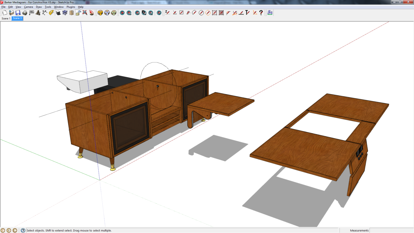
Ok, I've made a bit of a start on a 'for construction' version. I've had a go at adding bits of detail here and there. I've also allowed 2mm clearance around hinging and rotating parts. I still need to work on how to support the front hinge down panel when it is closed and open. I had an idea that the timber veneer sheets came in 1200mm wide pieces (which is why the top is 590mm deep) but I had no idea about length and thickness. I am now working with 19mm thickness.
Feel free to poke around the model. No dynamic components in this one though. Thanks for all the help so far. Before now, I didn't even know what veneer was.
-
Good start.
I made some modifications to your model.
I corrected some of the component definitions and axis orientations. I also added some of the edging. Note, on the vertical dividers, I modified them to make them easier to construct and make the case easier to assemble. You moved the bottom up like I suggested but when the doors are opened you'd see the cleats the legs attach to so I made the edging for the case bottom wider. There's still some joinery to draw and the details on that rotating projector thing need to be worked out.
The first thing I would do for that is decide how you'll support that mechansim. Choose exactly which hardware you'll use. I would be inclined to use in-line skate bearings on the pivots. Once that part is figured out, you should be able to sort out how the front panel is supported. If you use the cam idea, you'll need a way to pull the panel closed while allowing it to open. Suppose that panel were split into two pieces. For the sake of discussion, an inner panel and a frame. Maybe the frame is hinged to the case and connected to the projector support so that the support can pull the thing closed. Then, if you need to open it manually, you'd open the inner panel only. I'd draw it but I'm running out of time to get ready for work.
By the way, I think I'd modify the way the doors are made a little. I don't think you need that thin plywood frame to be as wide as it is.
Barker Mediagram - For Construction.skp


-
Cheers Dave. The dark mesh does look good. Unfortunately my home theatre PC is black. The white was a nice touch though. I was actually thinking about skate bearings for the rotation. When there was a crank, the bearings would have been bigger but without it, there is no problem.
I'm not at my PC tonight so won't get a chance to look at your tweaks in detail for a few hours. Thanks again for all your help so far.
-
Sorry about the PC. I didn't catch the color change. I removed the materials from the components and groups and put them on the faces where they belong. I missed fixing that one, though.
-
The reason for the axis orientations being wrong is because I foolishly built the whole thing facing another direction. I guess this effects material orientation? Thanks for changing the the front to be easier to construct. What materials are all those front pieces made up of?
With the edging, I'm a little confused. I was researching and noticed that the standard single layer edging was just 0.6mm thick. I see that you've added 6mm thick edging. This is where I've been getting my info from:
In my lunch break today I'll add the bearings and have a think about the rotation. I've been toying with the idea of magnets for locking things into specific locations rather than locating pins. The inner and outer front panels is a clever idea for achieving the 2 functions of spring return and fully opened. I'll post my changes and concept sketches in a few hours.
-
I made most of the edging 6mm thick. that would be similar to the typical 1/4-in-thick edging that would be common here. It would be soild wood glued onto the edges of the plywood. It is more durable than that thin glue on edge banding and I think it looks much nicer. You can use a matching wood or a contrasting one. Some of the edging is thicker but in most cases it's all the same.
If you wrapped a steel band around the cams (the sides of the pivoting part) and put rare earth magnets in the hinged front panel so they contact the band, the panel would follow the cams as the top rotates and yet you could pull the panel open for access.
As to the axis thing, yes, mainly I corrected the axes to make applying materials with proper alignment at least more predictable.
I'll be interested to see what you come up with.
-
Added some more edging. Re-worked the rotation with magnets for holding the front panel to the cam. Added skate bearings for the rotation (not sure that this is the best method, but I had to try something). Added locating magnets for the rotation open and closed.
I also did a little work on the doors but I'm not all that happy with it. I'm not sure what I want it to look like to be honest.
Barker Mediagram - For Construction V3.skp

-
At least you can work it out in SU before committing to wood.
Do the side piece on the center section have to be shaped as you have them?
-
With next to no woodworking experience, Sketchup allows me play around with concepts and design variations at no cost but time. I'm not sure how you all coped before 3D modelling.
The side pieces don't have to be exactly like I have them but I do want them to be rounded for a gentler contact with the front panel (the circle in my model is the path of the rounded side). I guess the sides could be made up of 2 pieces, one for the pivot and another for the cam. The thin board between the cams is to hide the projector a bit and has to have a clearance gap for cables to pass through. I have some more ideas for this that I will work on a bit over the weekend (it's late Friday night here). This has been a very interesting and enlightening week.
Advertisement


