(Mechanical Engineering) Rotor design - WIP
-
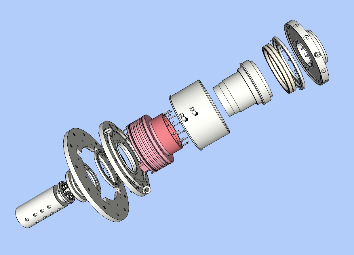
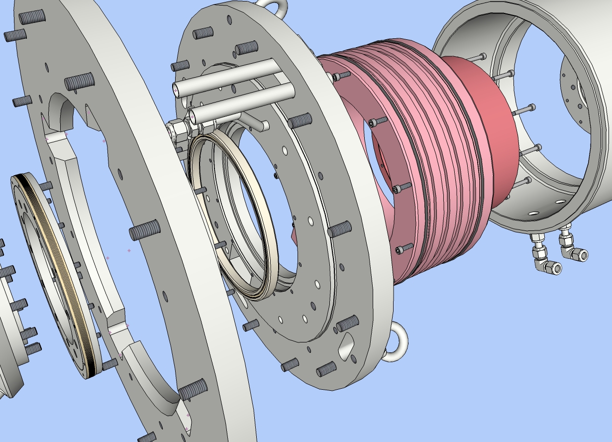
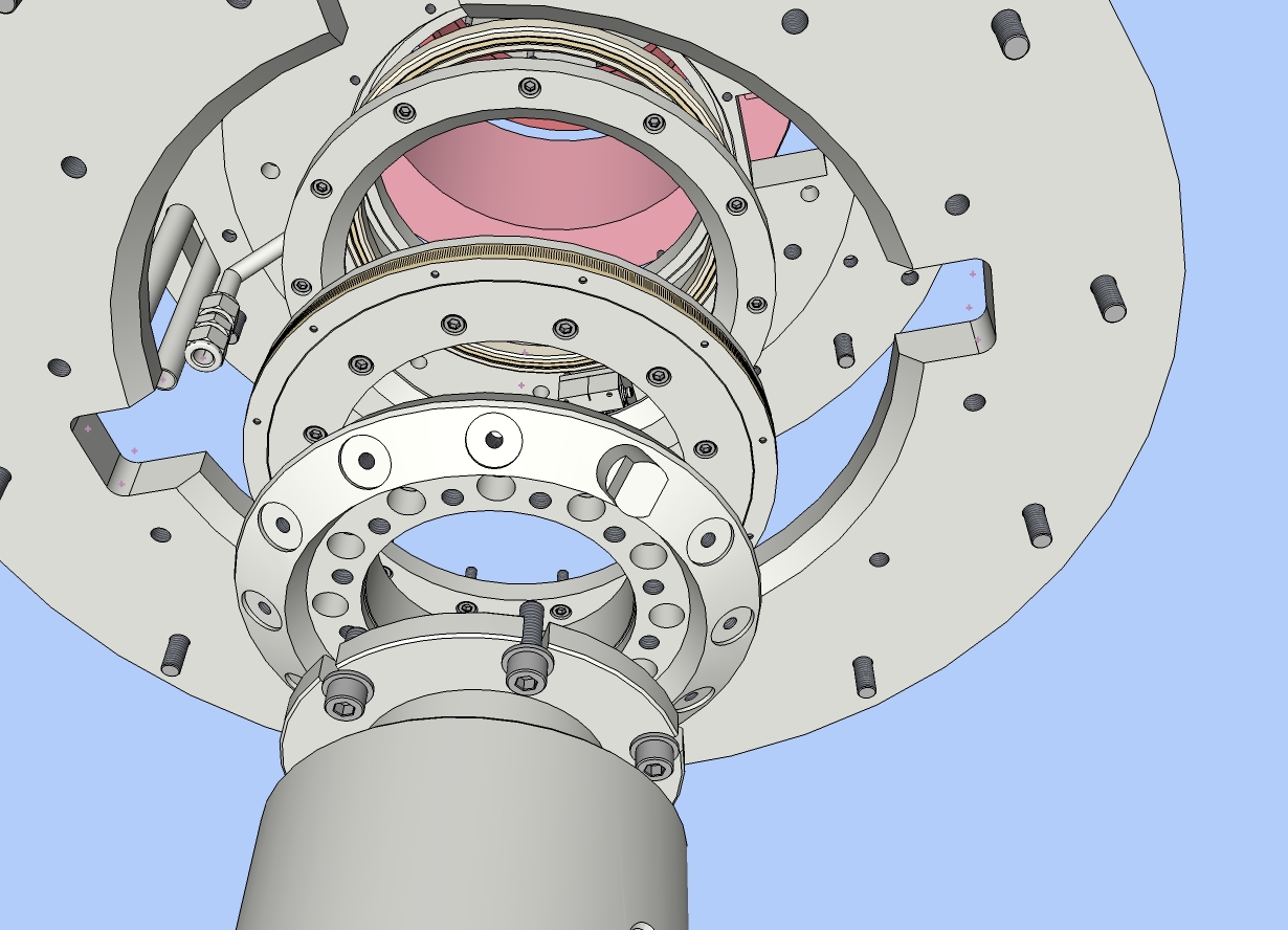
The attached images show a work in progress. The first image shows the elements of a rotor for a high speed rotating table. The hollow-shaft torque motor will rotate a support table and fluid tank at speeds of up to 600 rpm. The motor's stator and rotor are in two shades of pink. To give you an idea of scale, the stator (lighter pink component) is around 300 mm in diameter. The motor is water cooled, hence the two o-rings (black) and the cooling jacket. So far, all the design concepts have been done using native Sketchup and a few plugins. The detailed views show the optical encoder and the radial contact bearing. I find SU very useful for design studies prior to final detailing.
Regards,
Bob
-
Those are impressive drawings Bob. Your exploded views are great. Is this a prototype you plan on making? What is your job and background....just curious.
Cheers,
Jeff
-
Great attention to detail. I would only suggest taking your segments higher on your round objects. They are a bit faceted. Other than that it is nice to see how others use Sketchup.
Scott
-
Sure would be easy to get your point across to other development team members with a drawing like that. Nice work.
Wouldn't it be great to be able to just export the components to Cad/Cam. -
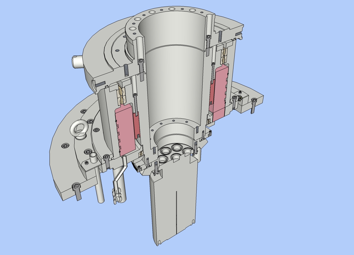
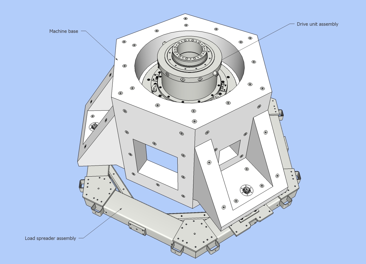
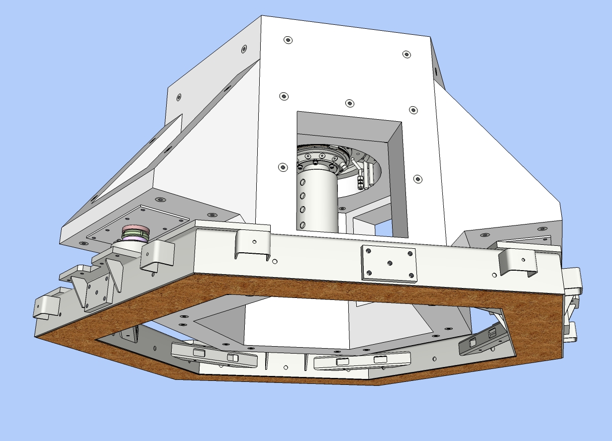
Here are a few more views. I used TIGs SectionCutFace.rb plugin to do the section cut through the rotor. The machine base is to be cast from polymer concrete and the load spreader distributes the estimated 1200 kg of load on the laboratory floor. We will be spinning masses of up to 200 kg at speeds of up to 600 rpm and so the machine base has to have a high moment of inertia and be very stable stable.
The last image shows the mould (US, mold) which will be used to cast the base. The M10 inserts can be seen with their hexagonal sections which anchor the inserts into the polymer concrete. I am using polymer concrete because of its high structural or hysteretic damping.
I try to use the minimum number of segments when drawing rounds. Usually, I use either 48 or 96 segments, depending on the complexity of the assembly and the size of the rounds. Tapped and clearance holes are usually drawn with the default 24 segments, or sometimes 12 segments; again, it depends on the size of the hole.
I work at a university and do design work for various groups. This machine is for the GPFD group (http://www.atm.ox.ac.uk/group/gpfd/research.html).
My motto is, "If I knew what I was doing I would be dangerous".
Regards,
Bob
-
So, nice. If only I had access to SU, 6 years ago when I was hand drawing illustrated parts manuals for go-karts.
-
Here is a view of the base after manufacture
-
The machine base was installed just before Christmas. The next step is to build up the drive motor assembly. Things should go a little faster now that the machine base is in the lab.
The assembly was designed using Sketchup, although I switched to a CAD program to complete the engineering drawings for manufacture.
-
Cool one!

Maybe my little plug (fragmentation) can interest you
@unknownuser said:
I switched to a CAD program
A Nurbs program?
-
Absolutely beautiful detailed modeling thanks for sharing hope to see much more great work

-
Dear Pilou and Dolphus,
Thank you for your kind words.
The final modelling was done in Autodesk's Inventor, but by then I knew exactly what I wanted to draw and so that part went very quickly.
Pilou, I didn't know about your plugin fragmentation. It looks very useful. Is there an English version too?
Kind regards,
Bob
Advertisement


